
Recently (years, not decades) LEGO introduced a new family of motors, sensors and control system – it was and is a bit confusing, but whether you think of LEGO WeDo, Control+, Powered Up, Spike Prime or the new Mindstorms 51515 it is all based around common backbone and, especially, a common connector – a 6-pole non-stackable plug.
Which, by sheer coincidence naturally, is completely incompatible with the old Power Functions connector from LEGO, who also claimed not to intend to manufacture an adapter cable because reasons.
Before someone jumps at me: I do understand WHY. And no, I don’t mean ‘to sell all motors again’. There is a technical reason not to make an adapter cable. You see, when the Power Functions system was designed, the main source of power was a dumb battery box. Even equipped with a cheaply made switch, a 6AA battery box can withstand all the power draw that stacked multiple motors can realistically take and it is the batteries that will fade before the box melts. With PoweredUp the world is a bit different. The basic box is a remote control receiver, so its outputs are electronically controlled. They have limited output power and for that reason it is necessary to limit the amount of power drains (motors) that can be connected to a channel. So they decided to limit it to one. I’d expect the lights to have a stackable plug though, as the LED lights take minimal power, but that’s a different story.
Okay, so what about that connector, or why am I writing this post?
The PoweredUp family has several very interesting motors with speed and position feedback, but at the same time it can power a simple motor like the old Power Functions M-Motor, with smooth power control even if without actual speed regulation. So it would be great to be able to just replace the PowerFunctions battery box with, say, Powered Up Technic Hub and gain smooth remote control of your existing creations, isn’t it? How about not needing to buy all motors over again? Sounds good? So why don’t we buy a few Powered Up connectors… wait, what, not available?
They are proprietary.
There has been some reverse-engineering going about and the most important findings can be read on the famous Philippe “Philo” Hurbain’s website, specifically here: https://www.philohome.com/wedo2reverse/connect.htm
What’s important for us is:
- The Powered Up system does not provide constant 9V output (so goodbye IR receivers and PF servos, you need the 9V supply!)
- The brick has direct motor output on pins 1 and 2 – we just need to connect the motor somehow
- To enable ‘dumb motor’ mode pin 3 (logic ground) needs to be connected directly to pin 6 and through 2.2kΊ resistor to pin 5 (‘WeDo 2.0 motor’)
Funny enough, even the dumb motors (like the WeDo 2.0 motor) have all 6 wires going to the motor and only there the identification wiring is done. In my case I opted to put all the components within the plug and lead out only the two power wires of the motor.
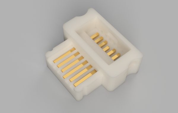
So I went ahead and designed a 3D-printable connector that is compatible with the Powered-Up sockets.
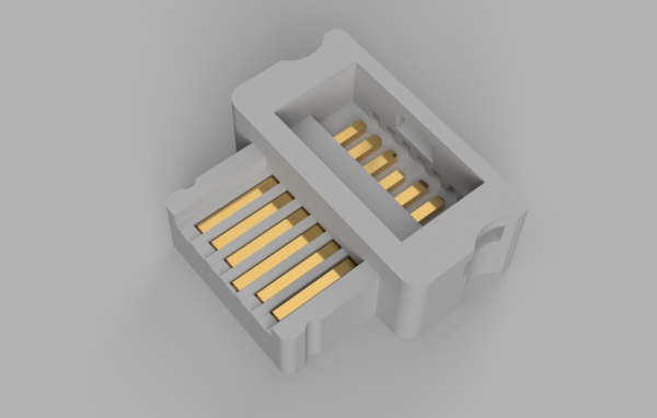
The size is exactly that of a LEGO connector, with one limitation: the LEGO connector has a cutout to let a folded cable leave the connector upwards making the depth when plugged exactly 1 stud. Since this connector needs to be soldered (LEGOs is crimped), it needs a tiny bit more space inside, so I opted to provide two exits for the motor cable: straight out or at 90° angle, you choose which way to build it depending on your preference and integration concept.
To make this connector you will need a very well calibrated and accurate 3D printer. The tolerances are tight and if the dimensions are even a bit off you will not be able to get the contact pins in.
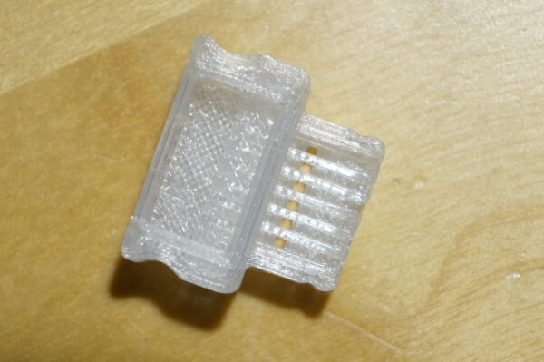
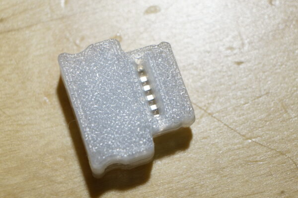
This is how it looks like when printed. There’s a slot on the underside the purpose of which will be clear in a moment.
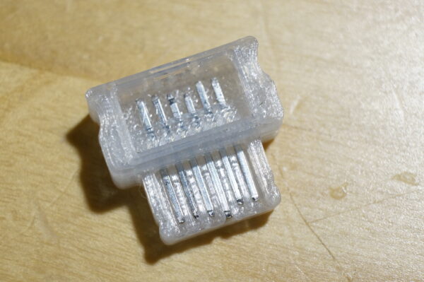
The electrical contacts are made out of pins pulled from a standard goldpin connector (0.6mm square pins). They are inserted from behind (from above in the picture) and need to be pushed in until they reach their stops. The ground pin does not have a stop, it should reach the front edge of the plug – ground shall make connection before other pins do.
Now the slot is there to put a drop of thin cyanoacrylate glue to secure pins in place. This is not a very strong fix, but will help pins from lifting. Don’t glue them just yet, as soldering will destroy the bond.
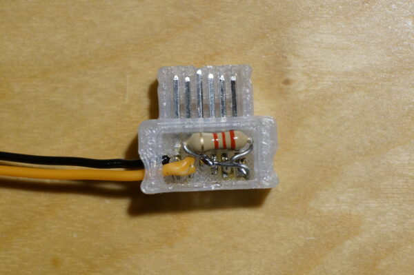
Now comes the hard part – and I do mean it’s really tricky to get it all soldered up. It’s tight. If you are not very proficient at it, it may be better to clip the back wall of the plug out.
From left to right: Motor A, Motor B, Ground, VCC (unused), ID1 (connected over 2.2kΊ to Ground), ID2 (connected directly to Ground). If you want your motor to act as if it was a train motor, connect ID1 to VCC directly, save the resistor.
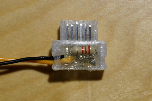
Since the place is so scarce, I opted against some sort of a lid and instead sealed the plug with UV resin. This way there’s protection against shorts within the plug and the whole thing becomes more mechanically stable. And let’s face it: it’s easier to reprint the plug than to disassemble it without melting the plastic in the process.
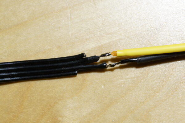
Whether you replace a PF connector on a motor or – like I did – cut a chinese clone extension cable in half to make an PUP-PF adapter, you need to use the two middle wires. The outer wires carry 9V constant power, which is not available with PoweredUp control bricks.
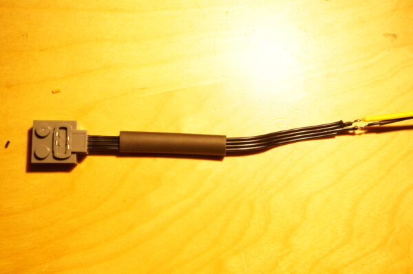
If you splice this plug into an PF extension cable, best keep the polarity like in the photo above. This way a PF M-Motor will behave exactly like the WeDo 2.0 motor does (spin direction wise).
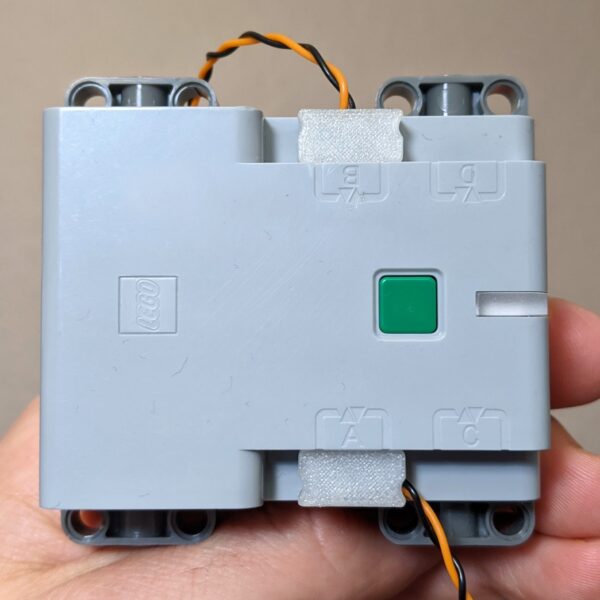
Voila. Now your WeDo / Technic / City hub will see your PF motor as a simple WeDo motor and you will be able to control it with your phone app or (City Hub) with a hand-held radio remote.
If you wish to try this yourself get the STL https://www.thingiverse.com/thing:5825237
(if you get 404 not found by clicking the link above, try https://www.thingiverse.com/mareklew/designs and look on the list of my creations, if this also fails, open manually Thingiverse.com first and then re-click the link)
Hi dear, how are you doing? Loved to see this adapter.
Will you publish it on thingverse?
KR
Hi, thank you,
as I mentioned above, right now I don’t want to publish it, especially not on Thingiverse. But if there’s interest I can provide these either printed or share the design in a private channel.
Thanks, but I don’t want to put it on Thingiverse…
1/ There’s too much stuff lifted off Thingiverse and used for commercial reasons, I avoid posting there things that I put a lot of effort into making.
2/ I’m not entirely clear about their terms and conditions of their right to use posted designs.
3/ I’m not sure if LEGO has some protection on features of this plug. I did not copy their design features, my connector is designed from scratch to mate with their sockets, but still, there may be some geometry that they managed to protect and I don’t want trouble from posting my design files online.
This is great. We were looking for a way to print the connector. Can you share it with me please?
Check your mail 😉
Check mail
see mail
Looks really cool. I’d love a chance to give it a go myself.
Did you get the email?
Hello – great looking plug – I’d like to give this a shot. Sounds like I need to post here to request the file? Thank you!
Actually, should be enough to message me on euro bricks, but if you did i didn’t get a notification :^)
You got mail
Z doĹu proszÄ, mail poszedĹ 😉
Check mail
Check mail
Thanks a lot for the design and for sending me the files! I already printed and soldered 2 of them and they work remarkably well. Using PETG even soldering (which I was concerned that it might be a problem due to the heat) worked without any issues. And my sons are very happy about the additional LED lights for their LEGO train and will even be more happy with the two N20 motors to come 😉
If you see any chance to make the connectors available publicly then people would probably really love them, but I can definitely understand your concerns.
A few technical notes:
– I really like your idea to use standard pins for the metal parts!
– LED lights: Connect ID1 through a 2k2 resistor to GND and leave ID2 unconnected. Power will be on pins 1 and 2 as for motors, but with a different ramp profile (i.e. they start with a lower voltage). Also, power will go up until the full battery voltage, so an appropriate resistor is needed for the LED(s). And even reversing seems to work, so e.g. for a train a red LED in the back and a white one in the front (connected with opposite polarity) should work.
– For testing I made myself a fully connected cable with jumper pins at the end. I cut out the back of the connector with a knife and then soldered all pins to 6 open wires of a standard jumper/breadboard cable.
– To seal up the soldering area and to fix the cables, I used UV activated super glue with also seems to work very well and really is dry in a matter of seconds.
– Just in case anybody is interested in trying it out – there is a project on GitHub to emulate Lego sensors using an Arduino: https://github.com/ahmedjouirou/legopup_arduino
Thank you very much for your feedback! Especially about PETG working too, that’s good news. Interesting observation on the LED thing, I have to try it out!
Right now the connectors are available semi-publicly. Every single person who cared to write me a comment here, email or in any other way asked for the file – got it. Of them all I got any sort of feedback from all of two… And it really helps to know if a design is printable and usable for others!
You’ve got mail…
That’s one mighty polite way to ask…
You’ve got mail…
Check mail 😉
Hi.
Would it be possible to get a copy of this file please.
And do you have the female end too?
Thanks.
check mail 😉
My own end is definitely male only 😀
a PoweredUp receptacle can be purchased online, so I didn’t care much to design a replacement. The issue is, the female part is the one with spring contacts, so it’s hard to jury-rig reliably.
Really? Where can you buy the receptacle?
Regards
Aliexpress or eBay… just don’t get fooled into buying loose plugs – they 99% of the time come without the metal contacts…
Check mail 😉
Check mail 😉
Hi,
check mail 😉
Check mail 😉
hi,
check mail
hi
check mail
Very nice work and description Marek,
Could you please share the model in a step format for further modification?
Kind Regards
Held Frodo
Hi,
sorry, but I don’t want to share design files right now.
ok. understood.
could you please either provide the final design?
Kind regards
Held Frodo
Hi Marek,
Well done! I’m trying to find out some cable extender for my lego power up models and the only one, which I found is too expensive for such
a piece of cable with two connectors.
So I decided to print my own connectors and make my own extender. Could you please share your design with me. I will try to draw the female connector, build the extender and if it will be successful, I will then share my female connector with you.
Many thanks in advance.
Josef
got mail…
check mail 😉
check mail
check mail
Hi Marek,
The connector look great and also the idea of using pins available in electronic components. Having a few PF1 elements and this being end of life, I would like to try to make an adapter like yours to drive PF1 motors with the BT Hub.
Is it possible to share the SLT for the connector?
Thank you!
You got mail
You got mail… sorry for delay
Siehe Mail 😉
Hello Marek! Thanks for your posts!
Could you share the model with me please?
I want to use it with third party servo motor with 515… masterbrick. For my project, the original medium servos are too loud.
I saw you can hack the old ev3 and maybe there is a way to do the same thing with the new robot inventor set.
Thank you for your response and for your help, have a nice day!
-> mail
-> mail
There’s a project out there that did exactly that. But you have to order the pcbs on thin stock. Look on Eurobricks forum for the guy who did it.
You got mail 😉
should be in your mail
hello, this connector is fantastic.
you can pass me the STL file to print it?
I want to put lights to the trains. From the comment above, I understand that for LEDs I have to use the resistor?
Sorry for my bad English but I’m Spanish. Thank you!
On Philo’s website there’s a table on which pins to connect to emulate which device:
https://www.philohome.com/wedo2reverse/connect.htm
for LEDs you will need 2.2k⌠resistor on one pin and no connection on the other (see the table on Philo’s page)
STL file is in the mail
Yep. Siehe Mail. GruĂ!
thank you so much!
I printed your connector and its really fantastic!
I was doing tests and I can connect the LEDs directly to GND and VCC to get 3.3V for the LEDs
In this way the LEDs light up when you turn on the HUB and are always on. They do not need resistance because it is the working voltage of the LEDs
the bad thing is not being able to control them with the control, but so with a control I can control 2 trains
can this connection damage the hub?
my idea is to have several LEDs on each train (I want light on all the wagons)
thank you!
Yes, you can manage the hub by this connection, it’s wrong on at least two levels:
1) LEDs need series resistance or other means to control current. Connecting LEDs directly to a voltage source is a bad idea.
2) the 3.3v line from the hub is for logic supply only. As long as you draw only a small current (under 50mA should be okay without knowing exact spec of the hub) you should be okay, but to power larger number of more powerful LEDs will damage the hub. The power lines (motor) are controlled by much more powerful drivers and do can source more current (in the range of few hundred ma)
thank you
I just connected two wagons perfectly passing the current through the magnet.
now it’s time to connect on engine line 1 or 2 for now with a resistor until you get a voltage regulator or transistor.
Hi, I want to make an extension cable for powered up as I’ve seen the ones on PV Productions but I’ve run out of pocket money.
I’d be interested in the stl if thats ok, and I’ll model the socket for the other end, (nicest sense it would save me half the job 😀 )
You’ve got mail!
Keep me posted on the work on the receptacle pls!
M.
Interesting work ! How about connecting and controlling the PU\WeDo2.0 motor with EV3 using a cable ? I know the cable isnât available but may be you can help make one ? Thanks in advance for this 🙂
Hi,
That’s unfortunately not directly possible.
The ev3 motors interface has the position sensor decoding in the ev3 brick. Inside the motor there are ‘naked’ quadrature sensors, the pulse counting is done inside the brick. PoweredUp motors have the pulse decoder inside the motor, the data is exchanged with the brick over a serial interface. Ev3 cannot even natively operate a dumb motor, because if there are no pulses coming from the motor, the brick considers the motor to be blocked and powers the motor off automatically.
Ev3 brick has serial interface available on the ports, but you would have to write your own motor control routine – should be possible under Linux, but rather out of question for the original firmware. Under Linux/python you could use the PoweredUp motors as simple uncontrolled motors too.
Hi it is Ian I was in contact with you on the Powered Up LEGO Facebook group, requesting the the 3D printer file.
Thank you.
Dear, your connector could save me this little bit of hair I have on my head. ;-).
I need to light a locomotive and maybe a wagon for the children (actually myself), and the idea of an independent power supply or hacking the hub is not an option that would satisfy me. But this printed connector of yours gave me back hope.
Consequently, I would love to accept STL for Powered Up connector in my mailbox. Be kind and send it to me.
Thanks in advance!
Dario
See mail!
Check mail
Check mail…
Check mail…
Check mail…
check mail
check mail
check mail
Nicely engineered. Could you send me the STL. I ordered crimp lpf2/wedo2 connectors. For making my own crimping tool, I maaybee can use your 3d design.
Check mail.
If you ordered crimp connectors pls. write if you got the metal contacts with them. I’ve seen many sold without the actual connector parts…
Hello Marek,
good job you have done here! The model looks great on the photos. Would you mind sharing the STL model with me so I can test it on my 3D printer too?
I wonder whether you also tried to model the socket for the connector? If yes, model would be great. if not, i will try to do it on my own. By inverting the plug and some adjustments it should be fine I believe 😉
Keep up in good work and have a nice day!
Check mail…
No socket. Sockets can be bought ready made, also, socket has the spring part of the connection, so it’s hard to make a guaranteed contact. Wonky contact, especially on GND, can damage your system, so I’d rather use a proper socket.
Check mail
check mail