Mindstorms EV3 and their motors
The LEGO Mindstorms™ is a very nice compact and easy to program set, with a lot of sensors (both, LEGO own as well as third-party, see e.g. http://www.mindsensors.com/).
When talking about motors, the air gets thin pretty fast. I mean, the LEGO own motors are cool, but there are only two sizes that are compatible with EV3 and the bigger one has rather sloppy gears, so although LEGO claims it has 1° of accuracy, it has easily 10° of (undetectable) backlash, meaning it can be considered halfway precise only if it is always loaded in the same direction – which for a two-wheeled tank-style robot is never the case.
So it got me thinking: how hard can it be to connect a third party motor?
The internet is full of topics on how to connect a PowerFunctions (PF) motor to EV3 or NXT, but this is not the thing here: I do want position control, so any hacks allowing for running an unsensored motor on EV3, while interesting in general, are rather pointless here. This is on how to get a third-party encoder-equipped motor to run on EV3
How does the EV3 control its motors?
There’s quite an extensive documentation on this topic available directly from LEGO website: https://education.lego.com/en-us/support/mindstorms-ev3/developer-kits – scroll down for the Hardware Developer Kit, which is a bunch of PDFs containing all the schematics of all the LEGO modules and a document describing the principles of operation.
Basically the whole smartness is incorporated into the EV3 brick. The motors are dumb, besides having an integrated optical quadrature encoder (slotted disc type, just like in the old computer mice that still used a ball to track motion, I know I’m dating myself now…). The motor driver, as well as position counters, speed and position control, all happen within the EV3 brick. This has both, advantages and disadvantages for my project.
Advantages are, I should be able to connect pretty much any DC motor with an integrated encoder board more-or-less directly to the EV3 brick.
Disadvantages are, if you fry the power stage, you have fried the EV3 brick, the output power of the EV3 motor drivers isn’t exactly overwhelming, and the motor voltage available is only about 9V (or less, depending on what battery you use). You could, however, use the brick output to drive a bigger power stage with external supply, although getting motor coasting to work would be a bit tricky.
There’s an interesting discrepancy in documentation: The driver chip within the EV3 brick is, according to schematics, an LB1836M dual motor driver (I haven’t opened the actual brick to check). There are several manufacturers making this chip, but they all agree on one thing: this chip provides 400mA per channel, 1A peak. Output voltage plots cut at 500mA, anything beyond ist outside spec. At the same time LEGO claims, that the EV3 brick can output 700mA per channel continuous, 1A peak. Whichever way, the driver has internal protection against overheating and should it fail it’s cheap to replace (provided you can solder SMD components).
On a side note, once you see the schematic, it gets really clear why all LEGO designs consistently use ports B+C (or A+D) for running tank-style robots: Channels A+B share one driver and channels C+D share the other driver chip, so it’s best practice to load both driver chips at 50% capacity instead of running one at 100% and idling the other.
The schematic will take you only so far, because it can’t possibly be the final (and proper) version, there are reports on some chips missing (to quote “There is also a PIC microcontroller (U28) and MFi authentication chip (U29) on the actual EV3 that is not on the schematic.“) and the detection logic for motors appears not to match the detection script described in the hardware manual.
Checking the schematics for large and medium servo motors one can easily spot the only difference interface-side: the value of series resistor in the pin-5 wire. So without further ado, let’s copy the design and be done with it.
connecting the motor
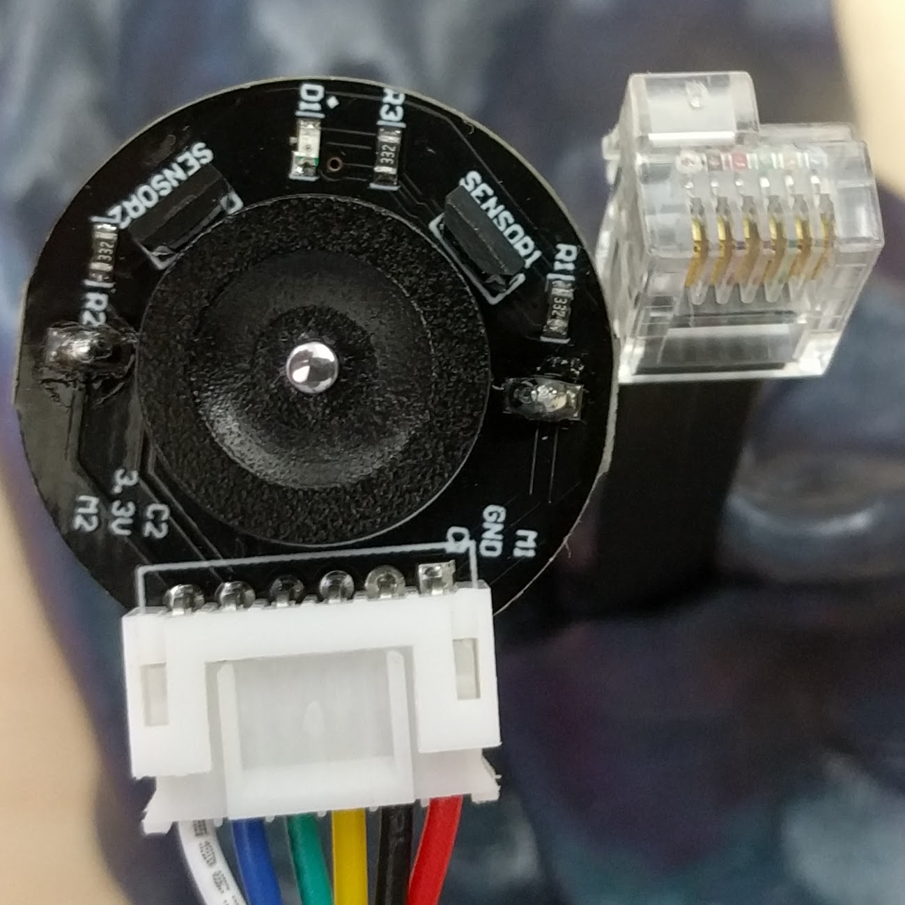
In the photo below you can see the backside of a geared motor with sensor (DFRobot FIT0521, ASIN: B0756NNM9K, be careful: this motor has stall current of over 3A, so it can easily overload the EV3 brick!) and the tip of an EV3 plug. The encoder is hall-effect magnetic type and can be interfaced to EV3 directly. Most small encoder motors will fall in this category.
To wire it to EV3 you will need:
– a sacrificial EV3/NXT cable, just cut one in half and you will have enough for two motors (the cable is identical on both ends).
– two 3.3kΩ resistors (or 3.3kΩ + 8.2kΩ if you are going for “medium servo motor”)
– preferably a 0.5A polyfuse (resetable fuse) to protect the brick from overload
The pinout of the EV3/NXT plug is (from left to right, when viewed as held in the photo):
1: motor positive (M1/red on my motor): put a 0.5A resettable fuse in series if you can find one.
2: motor negative (M2/white on my motor)
3: encoder ground (GND/black on my motor)
4: encoder 5V power (3.3V/blue on my motor) – note, even it says 3.3V on the board, the encoder is 5V-compatible, as the datasheet from DFRobot says
5: encoder A signal (C1/yellow on my motor): connect a 3.3kΩ resistor in series (in-line) here (between encoder C1 and pin 5 on EV3 brick).
6: encoder B signal (C2/green on my motor): connect a 3.3kΩ resistor in series (in-line) here (between encoder C2 and pin 6 on EV3 brick).
This connections will make EV3 recognise your motor as “large motor”.
If you’d rather have it recognised as “medium motor”, replace the resistor in Pin 5 connection with an 8.2kΩ one.
Commissioning and troubleshooting
Don’t just connect it and try running it right away! There are few things to check first, beyond the obvious: checking for all sorts of shorts. The EV3 brick is rather well protected against wrong wiring on the motor side, but care should be taken, as damage is still possible.
Power on your brick with nothing connected to it. Go to “port view” in the main menu (it’s in the third tab). Now plug your hacked motor in. It should get detected immediately, if it doesn’t check your wiring, especially the series resistors in the encoder lines (they HAVE to be there). My motor has a tiny LED on the encoder board, this LED should light up as soon as the motor is plugged in (even if it doesn’t get detected). If the motor doesn’t get detected, check that 5V power reaches the encoder board and that there’s some output voltage on the C1/C2 lines and that it toggles as you rotate the motor by hand.
Once the motor got detected, the ‘port view’ display will show a number next to the port. This number shall change as you rotate the motor by hand. It will go up when rotating the motor one way and down if you rotate it the other way. If this number doesn’t change or goes up-down-up-down by one (0,1,0,1 or 0,-1,0,-1 etc.) then either one or both encoder lines don’t register rotation, check your wiring and your hardware (i.e. sensor bent too close or too far away from the magnetic wheel on the motor).
Now you can go to main menu and select “motor control” to turn the motor on manually. It should spin freely.
If the above tests ran OK (and only if they did!) proceed to
checking the wiring polarity
Make a simple program consisting only of one block: simple motor move, rotate by, say, +20 degrees. Important: make this a small move. Run the program and check what happens:
A) motor moves in the expected direction (i.e. in the direction you would like to be understood as positive – it’s your choice whether it’s clockwise or counter-clockwise) at not too fast a pace and stops after a short moment. How far and how fast it exactly moves, depends on your hardware. For the DFRobot motor it will be about 1 motor revolution (seen on the encoder side, not on gearbox output). If this is the case, you are all set on the electric side.
B) motor moves in the expected direction, rather fast (at full speed, so to say), and doesn’t stop. You have to interrupt the program by pressing ESC. This means that the encoder counts in the wrong direction (i.e. the motor moves “up” but the encoder counts “down”). Swap encoder lines C1 and C2 at the motor side (i.e. if you put 8.2kΩ resistor on pin 5, it stays there, just the wires from motor side shall get swapped).
C) motor moves in the “wrong” direction (so in the direction you would consider “negative”), rather fast (at full speed, so to say), and doesn’t stop. You have to interrupt the program by pressing ESC. This means that the motor winding is wired the wrong way around. Swap the M1/M2 wires (the power wires) and you should be all set.
D) motor moves in the “wrong” direction (so in the direction you would consider “negative”), at not too fast a pace and stops after a short moment. This means you need to swap BOTH the motor AND the encoder connections around (so switch M1 and M2 around AND switch the C1 and C2 around. If you did put 8.2kΩ instead of 3.3kΩ on the pin 5 line, it stays there, the motor side wiring has to be swapped around).
Retry the test and if all is right, you’re done here.
Software side
The motor will respond to the normal commands from an EV3 motor block (large/medium motor, depending on how you configured the resistors). Positioning will be a bit trickier, as LEGO blocks assume encoder providing 180 pulses per revolution (the pulse decoder works in 2x mode, so 360 positions per revolution are decoded). The example DFRobot FIT0521 motor has 11 pulses per motor revolution and a gearbox with a non-integer reduction of 34.something resulting in, effectively, about 682 ‘degrees’ per revolution. Using the ‘revolutions’ mode of motor block is even less -intuitive, as the motor will spin once each ~1.9 ‘software revolution’. The upside is, this motor has next to no backlash in the gears, so can position rather precisely.
I have yet to figure out if it could be feasible to derive a custom control block to scale the position to reflect the actual degrees/revolutions.
The first part of the 2nd paragraph has bad grammar usage, can you fix it?
That’s a really helpful comment of the famous class: ‘it’s wrong, find out how’. How about making a suggestion?
Any idea what can be done to use the nxt to control external motor controllers with external power supplies? Like a electric wheelchair is what I’m aiming for. Cheers & Thanks
You can pick up the pwm signals at the port and feed them into an external motor driver. Question is, why would you want to use NXT for that? Just for controlling motors and some input device like a joystick an Arduino board would be more than perfect