
The Spike Color Sensor is often used for tracking markings on the floor in activities like FLL or WRO challenges. It is important to understand, that the sensor has a certain size of a spot that it watches. To determine exact dimensions of the spot I have built a test rig:
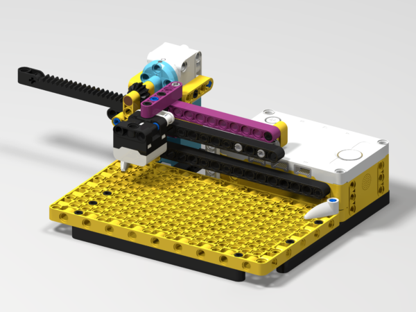
This contraption uses a rack and pinion mechanism to move a color sensor above a paper surface (not depicted), locating the sensor exactly 2 studs above it. The sensor is moved in small steps across the paper, on which black and white bars are printed.
The rack has 5 teeth per 2 studs, the pinion has 12 teeth, so one motor revolution equals to 12⋅2/5 = 24/5 of a stud. There’s 360° in one revolution, so it’s 360°⋅ 5/24 = 1800°/24 = 75°/stud. I made the motor step through 5° each step, resulting in 15 readings per stud.
This is the test program I have devised:
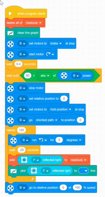
It moves motor against a hard stop at the maximum left, then moves it to absolute zero position. The full rack length is 1.75 motor revolutions, so it crosses the absolute zero twice. Still, if the model was assembled properly, the absolute zero position that’s closest to the leftmost sensor position is also the position where the sensor is centered above a stud, so a good starting reference.
Afterwards the motor goes in steps of 5°, so 15 steps to a stud, until it crosses 8 studs (the maximum travel of the toothed rack). After each move the motor is stopped and a reading is added to a plot (this can be later exported as a csv file).
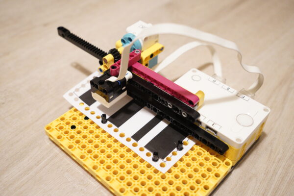
This is what it looks like in action:
The results:
I have run two tests. One with a 24mm wide black fabric tape strip, where the tape is really properly black. The second test was done with laserjet printed strips of 16mm and 8mm width (the tape was itself 20mm wide), the strips are slightly more reflective, than the tape, but could be printed in narrower widths.
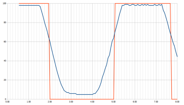
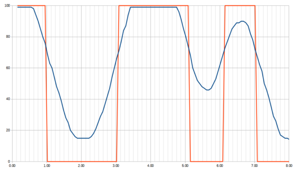
The following plot shows the ideal sensor reading (red) and the real sensor reading (blue) for a single strip of 24mm wide black tape.
The red line would be a ‘perfect’ sensor reading a tiny, tiny dot just under the lens. The real sensor watches a bigger field, so it starts dropping the reading once it ‘sees’ a little sliver of black line, then gradually goes down towards zero as more and more of the line covers the field of view of the sensor.
Since the bar is 24mm wide, and the sensor remains at minimum reading for about 8-12 mm (the sub-grid is at 1mm spacing, the major grid is at 1 stud = 8mm ≈ 1/3in. spacing) from this plot I’d estimate the field of view of the sensor to be about 12-16mm wide (about 1.5-2 studs).
A second run with 16mm and 8mm wide printed stripes:
You can see, that on the 16mm strip the reading goes down and stays at minimum for about 3mm, which would translate into a spot size of about 13mm (about 1.5 stud). The second strip, the 8mm wide one, is definitely narrower than the sensor’s field of view: the reading never reaches the minimum of the firs strip, the sensor starts seeing the white field after the strip yet before it stopped seeing the white before the strip.
Conclusion
It seems that the spot of the color sensor, when mounted 2 studs above the surface, is about 1.5 stud wide (1/2in or 12mm), give or take a bit.
Reproducing the rig yourself
If you wish to try it yourself, feel free to get the building instructions here (download button for the PDF below):